

Let There Be Light: Implementing Alec Lighting Control Suite
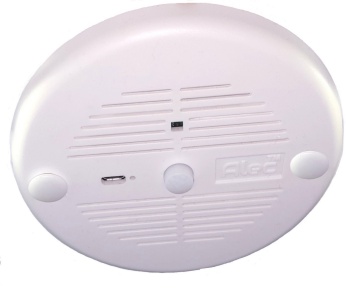
The beauty of the Alec Lighting Control Suite is its infinite scalability. Regardless of the size of the installation – from a small office to large building complexes or entire campuses, only 3 essential hardware components are needed to implement intelligent lighting controls on your premises:
(Please click on each component to access their product page)
|
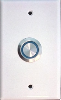
2. Push Button wall plate |
Light On Your Wallet: Alec Lower Installation Cost
In traditional light switch wiring, the main power is brought via special grade power cable through the wall to the switch and the output from the switch is then wired back to the lighting fixtures. Such jobs require licensed electricians and specialized tools.
With Alec, only low-voltage wirings are required to connect the push button switch to the ZC001. That means all you need is: – Very low-cost, low-voltage CAT-5 cables – a low-cost push button switch can be used to both turn on/turn off the lights as well as serves as a dimmer to control the light brightness level – No need for expensive dedicated dimmer!
All the lighting power wiring basically can take place up above the ceiling to the ZC001 and the ZC001 switched output is then connected to the lighting fixtures. This can reduce the wiring cost significantly since the licensed electricians are only required to handle the above ceiling wiring.
A lower cost apprentice may be assigned to handle the low voltage wiring from the wall switch to the ZC001 since there are no safety issues.

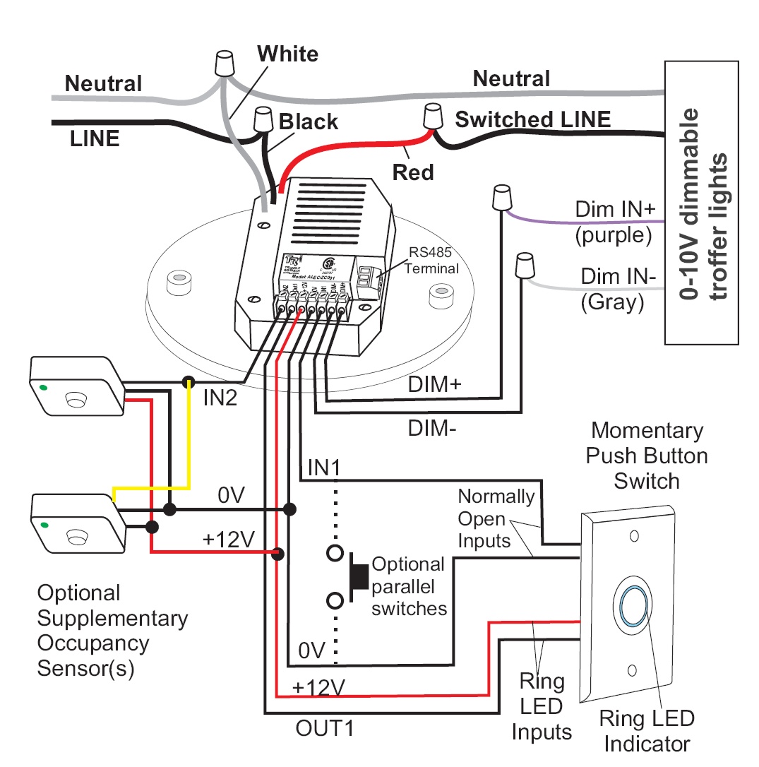
Simple Wiring For Alec-ZC001/ZC002
Alec-ZC001 & ZC002 wiring needs are extraordinarily simple. No training required – any electrician can install it.
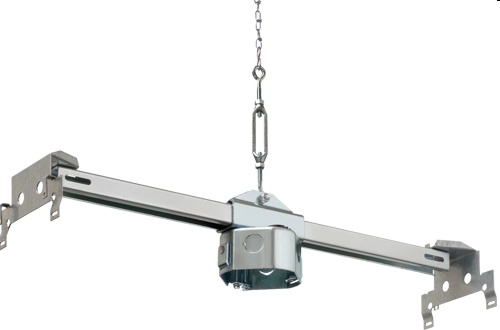
Note that to meet UL/CSA certification requirement, the Alec -ZC001 / ZC002 must be installed onto a round or octagonal shape junction box. For suspended ceiling you will need a junction box with T-Bar similar to the picture below:
|
In the next section we present a short explanation of the role of the optional supplementary motion sensor shown in the wiring diagram. |
|
Using Supplementary Motion Sensors For Large Zones
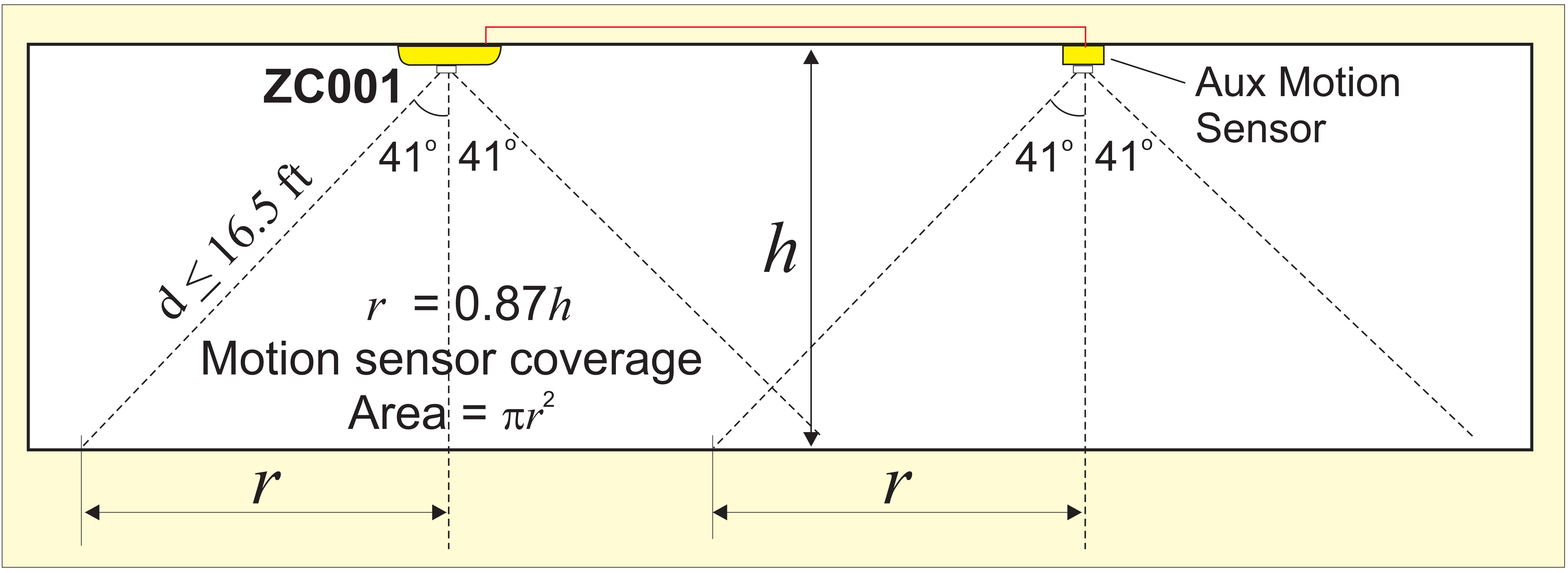
The Alec -ZC001 built-in motion sensor is highly sensitive and can sense motion up to a range of 5m (16 ft). However, this may be constrained by the coverage angle of the sensor and ceiling height – typically a ZC001 installed on a 9-ft high ceiling covers a circular area of approximately 200 sq ft centered around the ZC001. This coverage area is adequate for most rooms and individual offices.
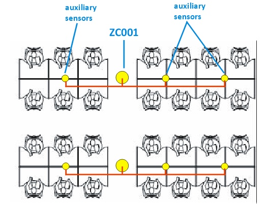
In large open office areas, we would generally recommend subdividing the area into multiple zones, each controlled by its own ZC001 so unused zones can be dimmed or switched off without affecting other zones. However, if a single ZC001 is preferred, or if there are high partitions that may block the view of the motion sensor, then one or more supplementary sensors can be installed in parallel to ZC001’s Aux. Sensor input, to expand the motion sensing coverage to as large an area as needed.
The MoSen-SR (standard range with 5m/16 ft range) and the MoSen-LR (long-range sensor with 12m/40 ft range) supplied by TRi are low-power supplementary motion sensors designed to work seamlessly with the ZC001. They can also be directly powered by the ZC001, which simplifies their installation.
However, any third-party motion sensor that can sink at least 2.5 mA current from the ZC001 12VDC supply may also be used for this purpose.
Installing Multiple Switches To Control The Same Zone of Lights
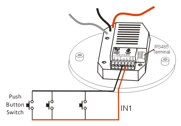
In traditional light switch wiring, if you need more than 1 switch to control the same light, then a 3-way switch wiring with a traveler wire connecting the two switches is needed. Adding more than 2 switches to control the same zone of lights would be a wiring nightmare and is seldom implemented.
Using Alec -ZC001, as many push button switches as necessary can be connected in parallel to the PB switch input of the ZC001 (see right).
Any of the push button switches may be used to turn on/turn off the lights as well as control the brightness of the lights in the zone. This save significant wiring cost, and additional switches can be easily added any time when the need arises.
Using Alec for Plug Load Control (aka Controlled Receptacles)
Since Alec supports both occupancy and time scheduling it can be readily deployed for plug load control purpose with incredible flexibility. Every individual workspace can be separately controlled by its own Alec ZC001 so that each occupant can have his/her own schedule of working and off-work hours.
If an occupant enters the work space during after-hours, or if the occupant were to stay for unscheduled overtime, the occupancy sensor can turn on the receptacle without needing to reschedule the work hour for that day. When the occupant eventually leaves the work space the receptacle will be turned off automatically after a scheduled time delay.
The switched output line from the Alec ZC001 could be used to directly power the receptacle and supply up to 10A of maximum AC load current. The energy consumption through that receptacle can then be logged by Alec ZC001 continuously for up to 20 years and can be retrieved for energy audit at any time. However, please ensure to mark the maximum current rating on the receptacle so that the user is aware of its maximum 10A load rating.
*Note: ZC001 has built-in over-current protection breaker that will cut output power if the RMS current >= 10.5A. ZC001 will automatically reset the overload circuit breaker after 30 seconds if that occurs. The maximum current for ZC002 (TRIAC output) however is limited to 2.5A.
If the receptacle needs to supply >10 A of AC current to the load, then its switched output can be used to control a high current relay or a 3 phase contactor to control high current receptacles that could be 120V, 240V or 3-phase devices. However, in such arrangements since the current does not pass through the ZC001 power metering circuit the energy usage will not be logged.
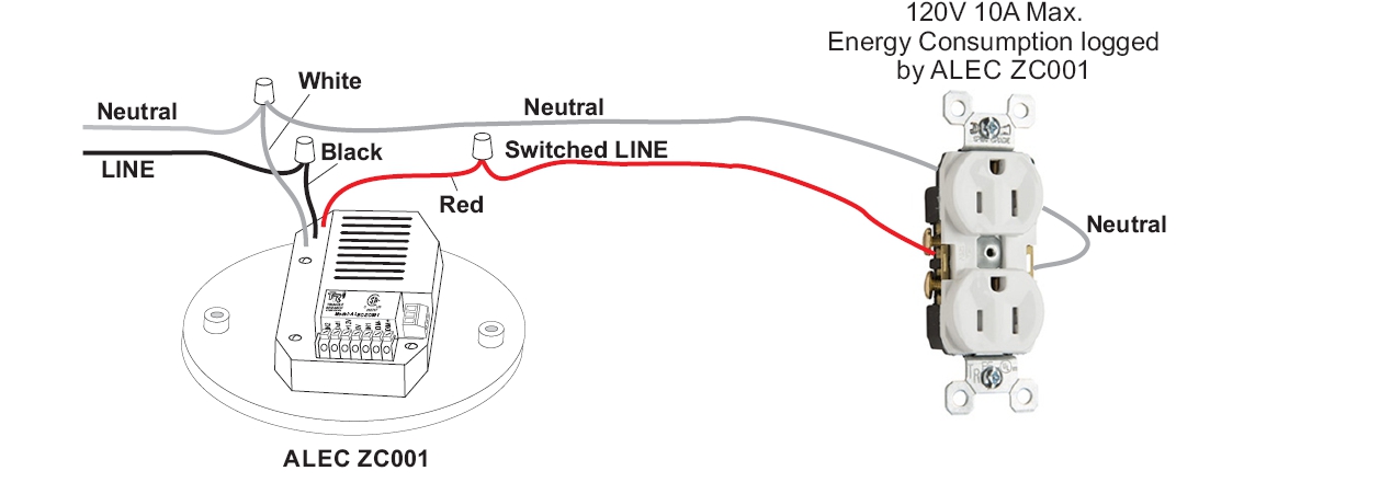 Direct Control of Receptacle. Energy Usage Logged by ZC001. Direct Control of Receptacle. Energy Usage Logged by ZC001. |
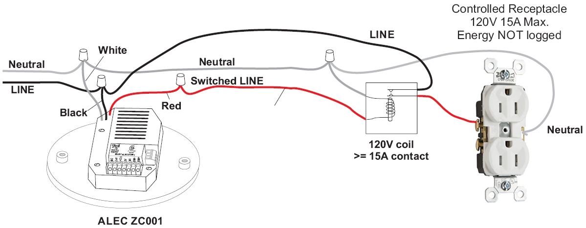 Control Receptacle with Higher Output Current. Control Receptacle with Higher Output Current. |
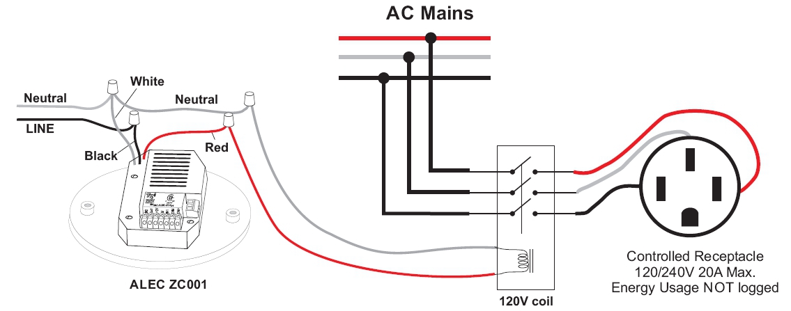 Control 120V/240V/3 Phase receptacles with Higher Output Current. Control 120V/240V/3 Phase receptacles with Higher Output Current. |