Select Installation Location
The single module ZC002 integrates a passive infra-red (PIR) motion sensor, a daylight
compensation light sensor, a kWh energy meter and a 32-bit microcomputer. It is designed
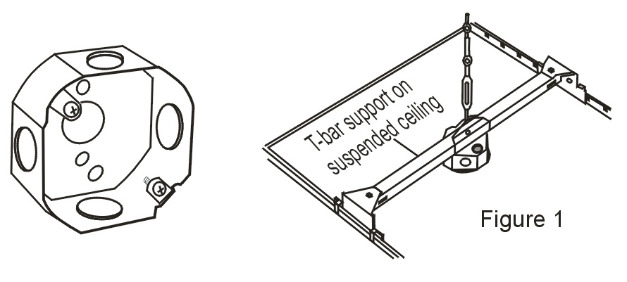
to be installed easily onto a 4-inch diameter, at least 1.5 inch(2-inch preferred) deep,
round or octagonal shape CERTIFIED electrical junction box similar to the following
picture:
Before installation you should choose a suitable location such that the motion sensor can
adequately cover the zone, and at the same time is preferably above a work space (e.g. a
work desk) where good lighting is essential. That would allow daylight harvesting function
to provide the optimum lighting to the work space.
Note that the built-in motion sensor has a maximum linear detection distance of 16.5 ft (5m), but has a field of view angle of 41o from the center line. So if the ceiling height is h and h < hmax, then the horizontal limit r of the built-in motion sensor from the center line is r = h*tan(41o) = 0.87h and the coverage area = π*r2 as shown in the following diagram:
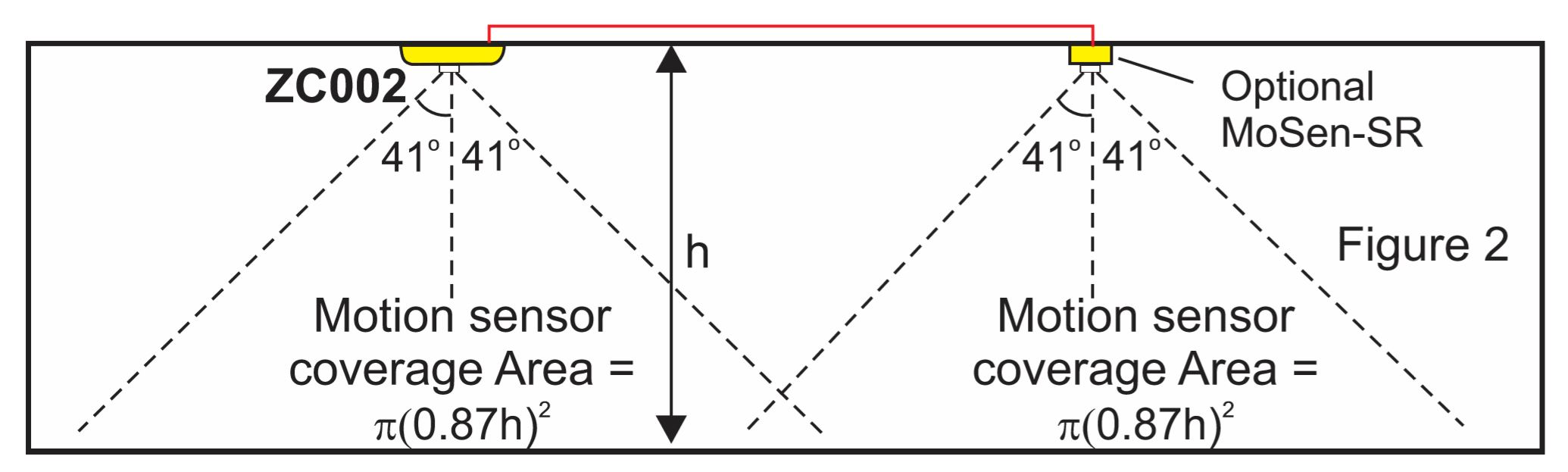
if h > hmax then the detection angle will be narrower due to the maximum of 16.5ft linear limit.
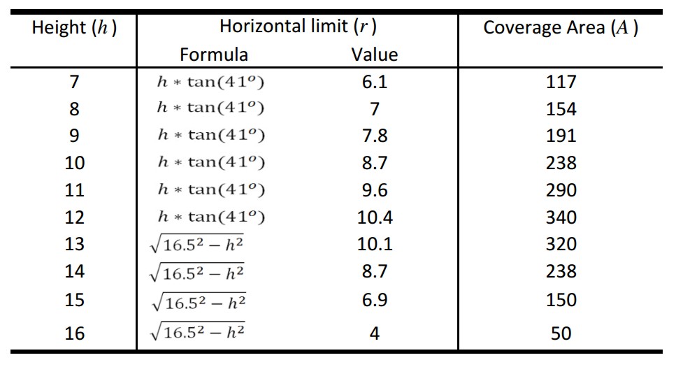
E.g. if h = 9 ft, r = 7.8 ft and the sensor covers a circular area
of nearly 200 ft2 around the ZC002. The following table gives you a quick reference of the
coverage area of the Alec-ZC002 for different ceiling heights.
If the lighting zone is larger than the coverage area of the built-in motion sensor, you
can add auxiliary motion sensors (e.g. the MoSen-SR) to the auxiliary motion sensor input
on the ZC002. For high bay installation you need to use a long range sensor such as the
MoSen-LR which has a range of 12m (40 ft). You may connect as many motion sensors as
necessary in parallel to the ZC002 auxiliary sensor input to cover a big zone.
However, to take advantage of energy savings opportunities, a big zone would best be divided into
smaller zones with each zone independently controlled by a ZC002 so that lights in
unoccupied zone can be dimmed or turned off.
The ZC002 provides sufficient current to power up to 4 auxiliary motion sensor MoSen-SR. However, if you need to connect more than 4 MoSen-SR you should supply an independent DC 5 to 12V power supply for these auxiliary motion motion sensors.
Daylight Harvesting Regulation - Please check with your local authority
E.g. ASHRAE 90.1-2010 defines the daylight zone as an area Depth x Width from the side lighting windows, where depth = windows head height (WH) unless limited by a permanent partition that is > 60 inches tall. Width = width of the window + 2 ft on each side, as shown below: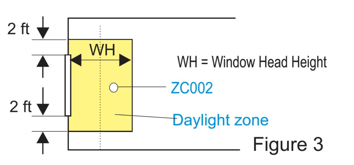
To avoid glare or reflection from windows that may inaccurately affect the light
sensor, we recommend installing ZC002 within the inner half of the daylight zone and above
a work space such as a cubicle or a work desk.
ZC002 employs industrial grade PID closed-loop control technology to maintain the lumen
(brightness) level of the area it controls. It achieves this by dimming the brightness of
the artificial lights proportional to the amount of daylight it receives.
More importantly, brightness are always adjusted in a very smooth and gradual manner
and will not brighten or dim suddenly, which can prevent annoying flickering that can
affect worker productivity and lead to user complaints.
The following picture illustrates how the daylight harvesting
works:
ⒸCopyright 2017 TRi, Inc
Once you have selected the installation location, use a hole cutter to cut a 4.125" diameter hole on the ceiling board and install the junction box. Then connect wires (see next section) and install the module into the recessed space of the junction box and fasten it using the two screws that are supplied with the junction box.
Power & Control I/O Wiring
Download 1: Recommended Wiring For New Construction |
ALEC ZC002 is powered directly by the AC main. The device contains 3 internal
isolated power supplies and provides a 12VDC for the low voltage control I/Os and a 5V
supply for the isolated RS485.
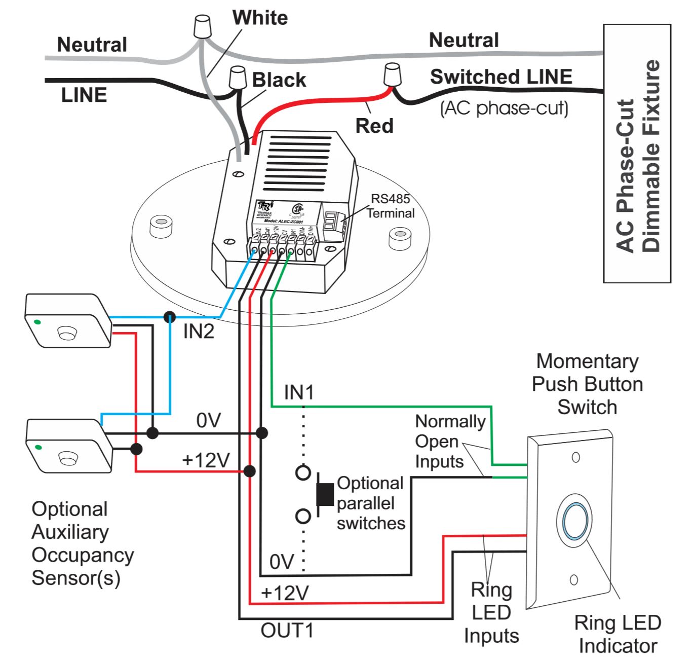
Connect the AC LINE to the BLACK wire and the neutral to the WHITE wire on the ZC002. The
RED wire is controlled by a relay inside the ZC002 and is used to supply the line power to
the entire zone of lights, as shown on Figure 4
| Power Supply | 110 ~ 240VAC |
| Device Current Consumption | 0.025A |
| Max. Rated LOAD Current | 2.5A |
| Dimming Output Type | Default: AC Phase Cut Dimming. Secondary: 0-10VDC, isolated |
| Max. Dimming Output current | < 20mA(source); 10mA(sink) |
| ON/OFF Light Switch | 12VDC @ 5mA |
NOTES:
|
Communication Wiring
1. Although a ZC002 works perfectly as a standalone unit to
control its own zone, the real power of the ALEC lighting system can best be realized by
connecting their isolated RS485 port to a ALEC-GW-E01 Gateway. The GW-E01 can turn the
entire network of up to 128 units of ZC002 into an IoT system and allows much greater
configuration capability using the ALEC Commander Pro Software.
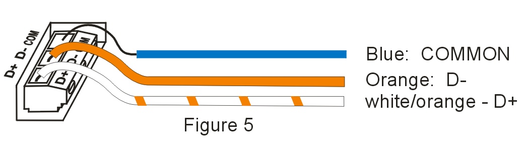
2. RS485 requires 3 wires for reliable communication; Namely: Data+ (
D+), Data- (D-) and a Common (COM) signal. All 3 signals are available on a detachable
3-pole screw terminals. See Figure 5.
3. We strongly recommend using 120 ohm impedance, Shielded Twisted Pair
(STP) cable to form the RS485 network. However, if STP is not available you can also use
CAT5/5e/6 to connect the RS485 ports. In the latter case we suggest using the white/orange
wire for D+, orange for D- and the blue wire for COM as shown in Figure 5.
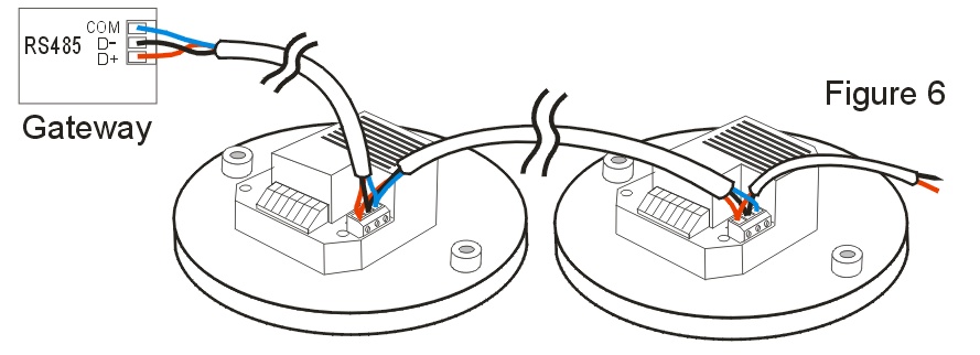
4. ZC002 controllers are networked in a multi-drop fashion. You
can simply daisy-chain their RS485 ports signals together using a shield twisted pair
cable or CAT5 cable as shown in Figure 6.
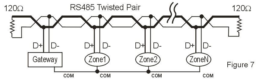
5. If the RS485 cable run between the first and the last device
in the network exceeds 300m (1000 ft) then you should add a 120 ohm resistor across the D+
and D- terminal at the last two 'corners'. This will allow the total cable run to extend
up to 1200m (4000 ft).
Using the ALEC-ZC002 Controller
All ZC002 are configured with the following default settings when shipped from the factory:
- Press the push button for 0.2s to turn ON light. Pressed for another 0.2s and release the push button to turn OFF light.
- When the lights is ON, press and hold the push button for 1 second to dim the brightness level of the lights down to the minimum of 1%. Release the push button and press and hold it for another 1 second will allow you to brighten the lights up to 100%. (Note: for some fixtures, adjusting below 10% may result in zero light output, while some other fixtures may not be able to dim below certain brightness level).
- Vacancy OFF is enabled - When the PIR sensor does not detect motion for 10 minutes or longer, it will dim the brightness of all the lights it controls to 10% brightness.
- Motion ON is enabled - When the PIR sensor detects motion the light fixtures will be brightened to the regular brightness (which is the last brightness set by the User using the Push Button or from the ALEC completely turn off the light, press the push button for 0.2s and then release the push button. The motion sensor will be blind temporarily for 5 seconds to allow the user to leave the premises without triggering the lights to turn on again.
- Daylight Harvesting is enabled by default, but will stay inactive until the user first calibrates the daylight control parameters based on the actual daylight the sensor receives.
- To calibrate the Daylight Harvesting sensor, turn ON the light and brighten it to the maximum brightness. Continue to hold on to the push button for 10 seconds until the lights is turned OFF and then release the push button. The controller will begin to calibrate the daylight harvesting parameters and the process should complete itself within 15 seconds.
Customizing ALEC ZC002 Controller
The above default settings allows ZC002 to be used right away in standalone
applications such as hall way, bike rooms, public garages, emergency walk way etc where
for public safety reasons the light will stay lit 24/7 but only at the lowest energy level
when no one is present (vacancy detection) , and whenever there are people present it will
brighten up to the full working brightness.
These default settings can be changed easily by the user using either the ALEC Mobile
Configurator app on Android, or via the free ALEC Commander Basic software that can be
down loaded from:
Temporary Motion Sensor Inactive Period
If your lighting zone is programmed to be turned ON by the motion sensor, the lights
will be turned ON to the regular brightness immediately when the sensor is triggered.
However, there may be time when you decide to leave the premises early and want to turn OFF the
lights completely by pressing the wall push button switch. What you would not want is for the
motion sensor to turn the lights back on right after you have turned it OFF.
To prevent this, the motion sensor will be disabled during the first 5 seconds
after the light is turned OFF by the push button switch. That is to give you time to leave
the range of the motion sensor before the motion sensor becomes active again
Temporary Motion-ON
When ZC002 automatic control time-out occurs and the lights in the zone are either dimmed down or
switch OFF, then within the next 15 seconds, ZC002 will monitor the motion sensor and if it senses motion the light
will be turned back to normal brightness even if motion-ON function is not enabled. This feature is called
"Temporary Motion-ON" and is useful to correct unintentional control action by the controller.
For example, say if your lighting zone is setup to be turned ON only manually but will be switched OFF automatically
when unoccupied for 5 minutes; Now if you happen to be sitting still in your office for a long time,
the light will be switched off after 5 minutes of no motion detection and you realize that it is not
what you want, you can simply wave your hand at the sensor and ZC002 will turn on the light immediately,
even though it has not been programmed to turn on the light by motion. Therefore you are not inconvenienced to
have to get up and go to the switch to turn on the light again simply because you have not moved for some time.
So how long will the light stay on when triggered by the temporary motion-ON action? The answer
depends on the current controller settings. If vacancy OFF is enabled then the lights will stay ON for
as long as there are motion detected within the Vacancy-OFF time-out period (5 minutes in our example). But
if vacancy-OFF is disabled then the lights will only stay ON only for 20seconds and ZC002 will attempt to turn off
the lights after 20s. The purpose is to give you lights temporarily so that you can walk to the wall switch
and turn ON the light manually if you intend to continue to occupy the premises.
Forced Manual Mode
At any time a user may overwrite the ZC002 automatic control function by forcing it
into a temporary FORCED MANUAL MODE as follow:
- Turn the light ON if it is not already ON
- Press and release the push button switch at least 4 times within 2 seconds. (It does not matter even if the light is turned OFF and ON while you are pressing the push button)
When the LED ring indicator started blinking once a second you would have successfully forced
it into a manual switch. Do the same to cancel it and return to automatic control mode.
The Forced manual mode is particularly useful if you want to prevent the motion sensor from turning ON
the light. E.g.if you would like to rest in a room that is programmed to turn on the light when motion is
sensed. Using Forced Manual mode you can temporarily override this action.
Forced Manual Mode Cancellation
If RTC is set, Forced Manual Mode will be automatically cancelled in the next scheduled time event.
If RTC is not set, Forced Manual model will be cancelled after the "Forced Manual Mode Max. Duration" time has expired.
LED Ring Status Indicator
On the standard push button switch PB01-BWS-1-there is a blue color LED ring indicator
around the push button serving as status indcator as described below.
| LED Indicator | Status |
Brighten up for 1 second when you enter the zone
|
The motion detector has detected you. (This feature is disabled when in Manual Mode) |
Blink rapidly for 2s every 30s
|
ZC002's Real-Time-Clock is not set |
Blinks slowly every second continuously
|
Switch in currently in the Forced Manual or *Scheduled Manual mode |
Blink rapidly continuously.
|
Over-current (>10.5A) breaker activated (breaker resets itself after 30s) |
Fully ON for 5s and fully OFF for 5s, repeat continuously
|
ZC002's internal power meter circuit is faulty. If it doesn't auto-recover within 5 minutes it may need to be replaced. |
*Scheduled Manual Mode
If you program a scheduled time to disable both the timer switch function and the
vacancy-OFF function, then the ZC002 essentially becomes a manual ON/OFF dimmer switch
(although it will still continue to support daylight harvesting if enabled).
We call this "Scheduled Manual Switch" mode.
In order to inform the user that ZC002 is currently behaving like a manual switch, the push button LED ring indicator will also blink ON and OFF every second similar to the "Force Manual switch" mode.
As you may expect, once the ZC002 enters into manual switch mode the only way to turn the lights ON or OFF is to
press the push button since all the automatic time-out functions are disabled. The ZC002 will stay in this
mode until the next scheduled time event when new settings take effect.
It is probably pretty rare to ever need to put the ZC002 into this mode but if you intentionally do so
please take note of the effect on the ZC002 behavior:
When ZC002 enters "Scheduled Manual Switch" mode, the lights will be set to the scheduled
brightness level. If the level is set to 0% the light will be switched off completely. For safety reasons,
the ZC002 will continue to monitor the motion sensor for the next 15s (temporary occupancy ON mode) and if it
senses motion, the lights will be turned back ON for 20 seconds. This is to give the user who happen
to be still in the zone some lights to walk to the switch and press it once to keep the lights ON.
If the user did not walk to the switch to press it on, then the light will be turned off after the
20 seconds time out. The user may wave to the sensor again to turn the light back on. This will be
repeated until either the 15s of temporary motion-ON period is over, or if the user manually press
the light switch once to keep it ON.